Logic gates
Categories: logic computer science
Modern computers, and many other electronic devices, are based on digital electronics. Digital electronic circuits are mainly composed of logic gates, which we will look at in this article.
The main CPU chip in a computer can contain hundreds of millions of logic gates, resulting in highly complex behaviour, but the operation of each gate is quite simple.
Digital electronics
An electronic circuit uses various components (such as transistors, resistors, capacitors, and others) to control an electric signal. In analogue electronics (such as an analogue radio receiver) a continuously varying electrical signal contains the information (for example, the sound of someone talking).
In digital electronics, the circuit is designed so that the electrical signal can only have two values. A low value (typically 0 volts) represents the value 0, and a high value (anywhere from about 1 volt to 10 volts or more depending on the system) represents the value 1. Information is processed by logically combining lots of 0 and 1 values, for example, to add 2 binary numbers.
AND gates
An AND gate accepts two digital signals as input and creates a single output. The gate expects its two inputs to each be digital signals (i.e. low and high voltages representing values 0 and 1). Gates are not designed to process intermediate voltages, so if the inputs to a gate are set to, say, halfway between the low and high voltage, then the behaviour will often be unpredictable.
In a complex digital circuit, most of the gates have their inputs connected to the outputs of other gates, which can be relied on to generate correct voltages as outputs, so incorrect voltages are not usually an issue.
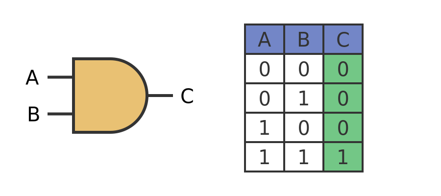
AND gates have the property that the output will be 1 if both inputs are 1, and in all other cases, the output will be 0. This diagram shows the symbol for an AND gate, with inputs A and B, and output C:
This symbol will be useful when we construct circuits from several connected logic gates to create more complex functions.
The table to the right of the gate symbol is called a truth table. It shows the state of the output C for every possible combination of inputs A and B. For an AND gate, as we noted before, the output is only 1 if both inputs are 1.
Notice that the values A and B are listed in a particular order. The value pair AB is listed in the order 00, 01, 10, 11. This is the correct numerical order if we treat the pair AB as a 2-digit binary number.
OR gates
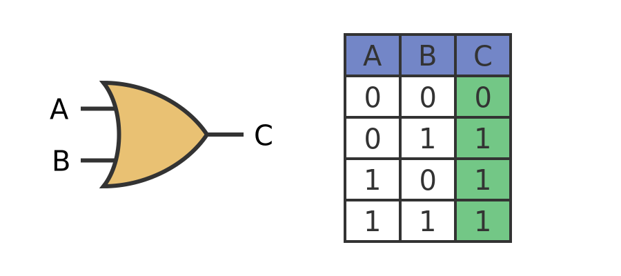
An OR gate is similar to an AND gate, except for the output rule. For an OR gate, C will be 1 if A or B, or both, are 1. It will be 0 if both A and B are 0.
Here is the symbol and truth table of an OR gate:
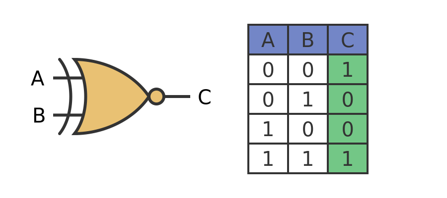
XOR gates
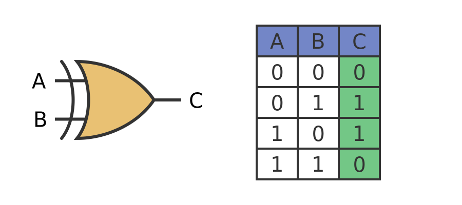
An Exclusive OR gate, usually called an XOR gate is another type of gate, with yet another output rule. For an XOR gate, C will be 1 if A or B, but not both, are 1. It will be 0 if both A and B are 0. It will also be 0 if both A and B are 1.
Here is the symbol and truth table of an XOR gate:
NOT gates
A NOT gate only has one input, A. The output B is the opposite of A. Ff A is 0, B will be 1, and if A is 1, B will be 0. This is called an inverting gate because the output is the inverse of the input.
Here is the symbol and truth table of a NOT gate:
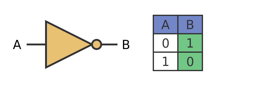
The small circle on the output of the gate indicates that it is an inverting gate. We will see this again in other gates later.
Notice that the truth table is only 2 lines long. This is because there is only 1 input, and that input only has 2 states.
Other inverting gates
A NAND gate is an inverting gate based on the AND function. NAND is short for NOT AND, and the gate functions like an AND gate followed by a NOT gate. Here is the symbol and truth table:
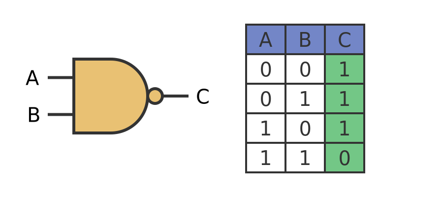
Notice that the symbol is the same as an AND gate, but with a circle on the output to indicate that the output is negated.
As the truth table shows, the output is 0 if both inputs are 1, but the output is 1 for all other values. This is the exact inverse of an AND gate.
A NOR gate follows the same pattern:
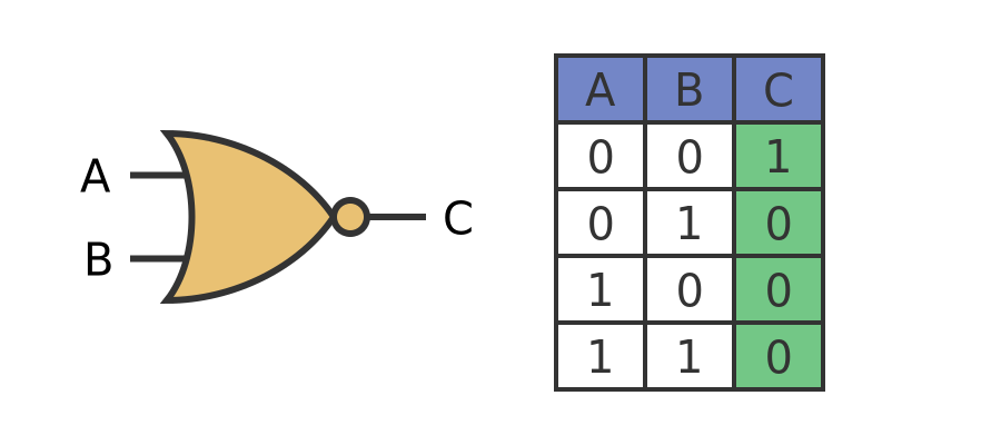
Once again the symbol is like the OR gate symbol, but with a circle on the output. C is 0 if one or more of the inputs is 1, and it is 1 if both inputs are 0.
Finally, here is an XNOR gate:
The symbol is like the XOR gate symbol with a circle on the output. The output is 0 if one input is 1 and the other is 0. It is 1 if both inputs are 0 or both inputs are 1.
Summary
The CPU of a computer is made almost entirely of these 7 gates. Collections of gates are used to store binary data, to compare, add, subtract or multiply binary numbers, to count in binary, to decode the binary instruction in a computer program, and to control and sequence the whole process. And many other things as well.
In future articles, we will look at how simple gates can be used to carry out some of those operations.
Related articles
Join the GraphicMaths Newsletter
Sign up using this form to receive an email when new content is added to the graphpicmaths or pythoninformer websites:
Popular tags
adder adjacency matrix alu and gate angle answers area argand diagram binary maths cardioid cartesian equation chain rule chord circle cofactor combinations complex modulus complex numbers complex polygon complex power complex root cosh cosine cosine rule countable cpu cube decagon demorgans law derivative determinant diagonal differential equation directrix dodecagon e eigenvalue eigenvector einstein ellipse equilateral triangle erf function euclid euler eulers formula eulers identity exercises exponent exponential exterior angle first principles flip-flop focus gabriels horn galileo gamma function gaussian distribution gradient graph hendecagon heptagon heron hexagon hilbert horizontal hyperbola hyperbolic function hyperbolic functions infinity integration integration by parts integration by substitution interior angle inverse function inverse hyperbolic function inverse matrix irrational irrational number irregular polygon isomorphic graph isosceles trapezium isosceles triangle kite koch curve l system lhopitals rule limit line integral locus logarithm maclaurin series major axis matrix matrix algebra mean minor axis n choose r nand gate net newton raphson method nonagon nor gate normal normal distribution not gate octagon or gate parabola parallelogram parametric equation pentagon perimeter permutation matrix permutations pi pi function polar coordinates polynomial power probability probability distribution product rule proof pythagoras proof pythagorean triple quadrilateral questions quotient rule radians radius rectangle regular polygon rhombus root sech segment set set-reset flip-flop simpsons rule sine sine rule sinh slope sloping lines solving equations solving triangles special relativity speed of light square square root squeeze theorem standard curves standard deviation star polygon statistics straight line graphs surface of revolution symmetry tangent tanh transformation transformations translation trapezium triangle turtle graphics uncountable variance vertical volume volume of revolution xnor gate xor gate