Creating a subtractor with logic gates
Categories: logic computer science binary
We previously saw how to add two binary numbers using logic gates. In that article, we developed a simple circuit to add two binary bits, with carry-in and carry-out bits. We also saw how to combine multiple single-bit adders to create a circuit that can add binary numbers together.
In this article, we will extend that to cover subtraction too. This is easier than you might expect. We will also look at how to make a single circuit that can perform addition, subtraction, and negation.
Binary subtraction
We covered binary addition and subtraction here. To recap, in the case of a 4-bit word, we can either treat it as an unsigned number or a signed number:
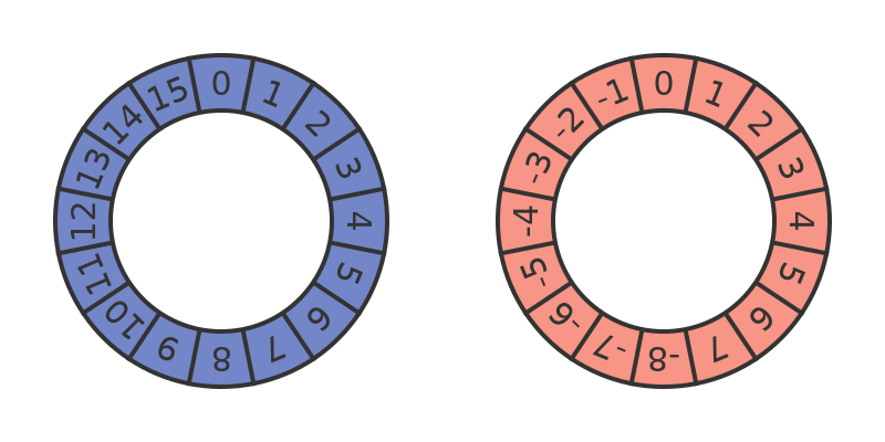
If we are using unsigned numbers, the binary numbers 0000 to 1111 represent denary numbers 0 to 15, following the normal binary notation.
If, instead, we are using signed numbers, binary values 0000 to 0111 still represent denary numbers 0 to 7. But binary values 1000 to 1111 represent denary numbers -8 to -1.
We can use this to perform subtraction by doing addition. For example, to subtract 3 from 5, we can add -3 to 5. Since -3 signed is equivalent to 13 unsigned, this wraps around to give the correct answer, 2:
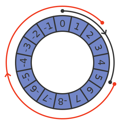
See the linked article for more details. If we look at the corresponding binary values we see this:
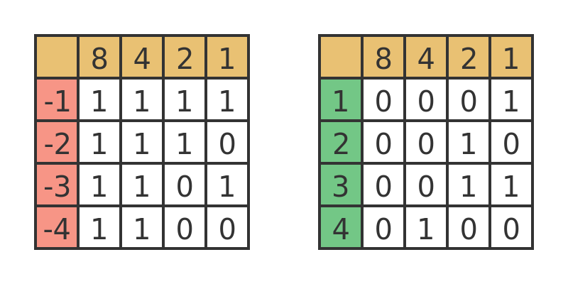
The negative numbers start at binary 1111 and count down. The equivalent positive numbers start at 0001 and count up. But there is a simpler rule for converting a positive binary number into the equivalent negative binary number. We simply invert every bit, then add 1. This is called the two's complement of the number.
For example, to find -1, we take binary 0001 and invert all the bits, giving 1110. We then add 1, giving 1111. Similarly, to find -4 we take 0100 and invert all the bits, giving 1011. Adding 1 gives 1100.
Binary subtraction algorithm
To summarise, to find A minus B, where A and B are signed binary numbers, we must:
- Invert all the bits in B.
- Add 1 to B,
- Add A and B.
The result will be a signed binary number representing the result.
Implementing subtraction with logic gates
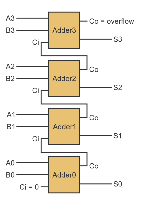
We already know how to add two binary numbers using logic gate adders, from the add two binary numbers. Here is the block diagram for a 4-bit adder:
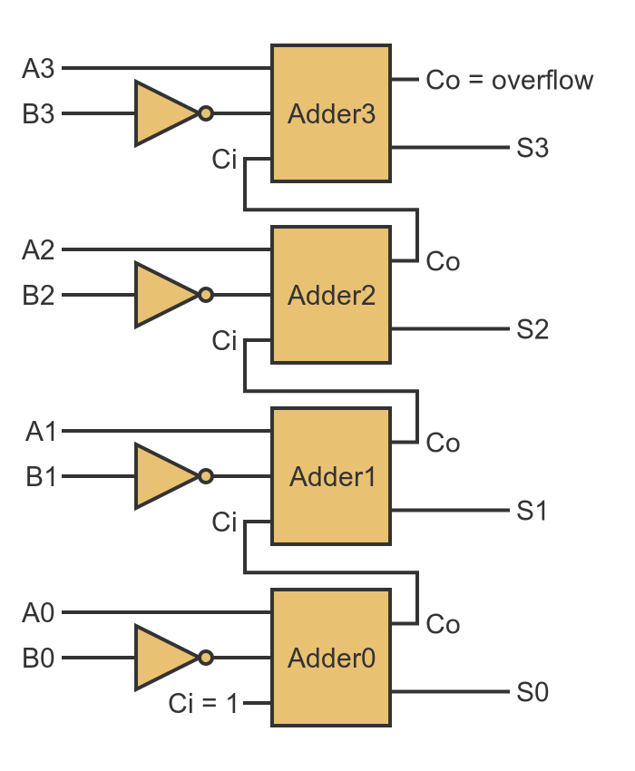
To subtract, we have to invert all the bits in B. That is not too difficult, we simply need to put an inverter (a NOT gate) in front of each B input.
We also need to add 1 to B. You might think that this would need another adder, but there is a little trick we can use instead. Remember that every adder circuit has a carry input that accepts the carry output from the previous adder. The carry input of the first adder is set to 0 because there is no previous carry value.
If we set that carry input to 1, it will add 1 to the result of A plus B. This, of course, is equivalent to adding 1 to B before adding it to A. So a subtraction circuit looks like this:
A combined addition and subtraction circuit
The addition and subtraction circuits are very similar. It might be nice to be able to use a single circuit that can perform both operations.
We might imagine an extra input signal, A/S, to control the mode, If that signal is 0, the circuit will add A and B. If the signal is 1, it will subtract B from A. To achieve that the signal has to control two things:
- The input carry signal for Adder0 should be 1 if A/S is 1, but 0 otherwise.
- Inputs Bn should all be inverted if A/S is 1, but not inverted otherwise.
For the first condition, we simply need to connect A/S directly to the carry signal for Adder0. This will ensure that the carry is 0 for addition and 1 for subtraction.
The second condition requires us to selectively invert each input signal Bn depending on the mode. The Exclusive OR gate (usually shortened to XOR gate) does this exact job. Its output is 1 if exactly one of the inputs is 1, but 0 otherwise. Here is the symbol and truth table:
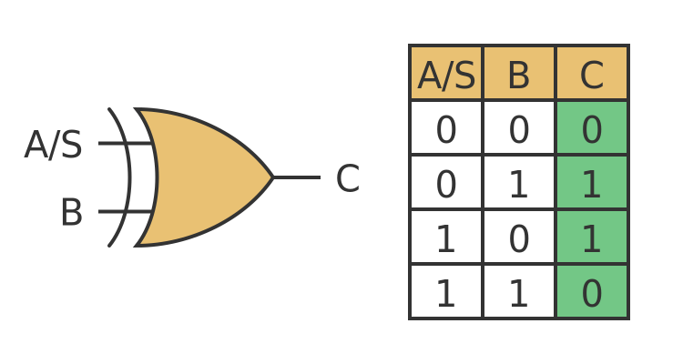
This does exactly what we want. When A/S is 0, the output C is equal to the input B. When A/S is 1, the output C is equal to the inverse of input B.
Here is our addition and subtraction circuit:
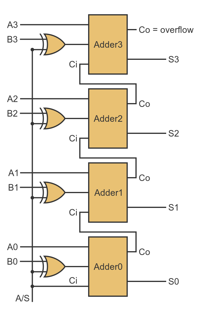
We have replaced each of the inverters from the subtraction circuit with an XOR gate. The second input of each XOR gate is controlled by the A/S signal, so it selectively inverts the B values for subtraction. The Ci input of Adder0 is also connected to A/S.
Negation
It might also be nice to be able to perform a negation, that is to find the value of -B. This is fairly easy. We simply set the circuit into subtract mode (A/S is 1), and ensure that the value of A is all zeroes. The output will then be 0 - B which of course is -B.
Related articles
Join the GraphicMaths Newsletter
Sign up using this form to receive an email when new content is added to the graphpicmaths or pythoninformer websites:
Popular tags
adder adjacency matrix alu and gate angle answers area argand diagram binary maths cardioid cartesian equation chain rule chord circle cofactor combinations complex modulus complex numbers complex polygon complex power complex root cosh cosine cosine rule countable cpu cube decagon demorgans law derivative determinant diagonal differential equation directrix dodecagon e eigenvalue eigenvector einstein ellipse equilateral triangle erf function euclid euler eulers formula eulers identity exercises exponent exponential exterior angle first principles flip-flop focus gabriels horn galileo gamma function gaussian distribution gradient graph hendecagon heptagon heron hexagon hilbert horizontal hyperbola hyperbolic function hyperbolic functions infinity integration integration by parts integration by substitution interior angle inverse function inverse hyperbolic function inverse matrix irrational irrational number irregular polygon isomorphic graph isosceles trapezium isosceles triangle kite koch curve l system lhopitals rule limit line integral locus logarithm maclaurin series major axis matrix matrix algebra mean minor axis n choose r nand gate net newton raphson method nonagon nor gate normal normal distribution not gate octagon or gate parabola parallelogram parametric equation pentagon perimeter permutation matrix permutations pi pi function polar coordinates polynomial power probability probability distribution product rule proof pythagoras proof quadrilateral questions quotient rule radians radius rectangle regular polygon rhombus root sech segment set set-reset flip-flop simpsons rule sine sine rule sinh slope sloping lines solving equations solving triangles special relativity speed of light square square root squeeze theorem standard curves standard deviation star polygon statistics straight line graphs surface of revolution symmetry tangent tanh transformation transformations translation trapezium triangle turtle graphics uncountable variance vertical volume volume of revolution xnor gate xor gate