Creating an adder with logic gates
Categories: logic computer science binary
An adder is a circuit, constructed of logic gates, that can add or subtract two binary numbers to give a binary result. In this article, we will look at how adders work.
Binary addition
We covered binary numbers and binary addition in earlier articles, It is worth familiarising yourself with these if you aren't clear about how to add binary numbers.
In summary, binary numbers use base 2, rather than the base 10 system (denary) we normally use in everyday life. In denary, the number columns represent 1s, 10s, 100s, and so on (powers of 10). So (of course) 162 means 1 times 100 plus 6 times 10 plus 2 times 1.
In binary, the number columns represent 1s, 2s, 4s, 8s and so on - powers of 2. Each digit can only have a value of 0 or 1. So 0111 binary is 0 times 8 plus 1 times 4 plus 1 times 2 plus 1 times 1. That is 7 in denary.
When we add two numbers in binary, we do it column by column, starting with the 1s column (just as we do in denary). Here is the example from the binary addition article mentioned earlier:
We perform the addition column by column:
- 1s column: 1 + 0 gives 1 with no carry.
- 2s column: 1 + 1 gives 0, with 1 carried over.
- 4s column: 1 + 1 plus the 1 carried over from the 2s column gives 1, with 1 carried over.
- 8s column: 0 + 0 plus the 1 carried over from the 4s column gives 1, with no carry.
So 0111 (7 denary) plus 0110 (6 denary) is 1101 (13 denary).
Binary adder
We could create a logic circuit that accepted 2 binary words and created a binary word as output. Using 4-bit words like the example above, the circuit would have 8 bits of input (2 times 4 bits), so the circuit would have 256 possible input combinations (2 to the power 8).
But of course, most modern computers use 64-bit words, or sometimes longer. Trying to implement this as a huge, monolithic logic circuit would be quite complex.
It is easier to break the problem down. We can start by design a simple logic circuit that just adds 2 bits together - 1 bit from a and the corresponding bit from b.
This circuit would require 3 inputs - the 2 bits that need to be added (from a particular column of a and b) and the input carry bit (from the previous column), It would create 2 outputs - the sum of the 2 bits, s, and the output carry bit that will be passed to the next column.
The adder circuit could be represented like this:
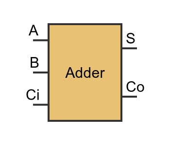
We often use a block like this to represent a set of logic gates that perform a particular function (in this case adding 2 bits with a carry in and a carry out). We don't need to concern ourselves with exactly how the internal gates are configured at this level (although we will look at that in detail shortly).
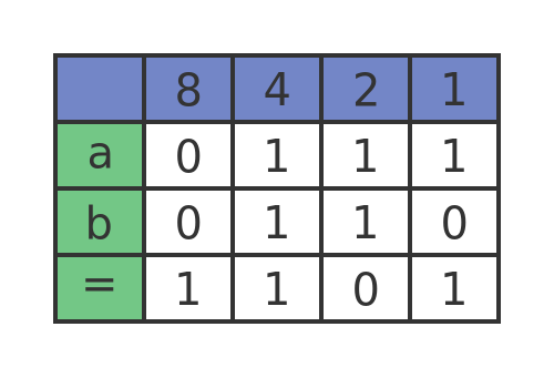
Overall, the box implements this truth table:
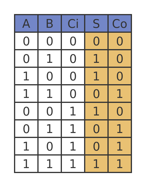
Essentially, the output bit S will be 1 if either 1 or 3 of the inputs (A, B and carry-in) are 1. The carry-out will be 1 if 2 or more of the inputs are 1.
Notice that the 3 inputs, A, B and Ci are all equivalent. They are just 3 binary values that the adder circuit adds together, there is nothing special about the carry input. The outputs S and Co are different though.
Adding words
To add two 4-bit words together, we need four of our 1-bit adders. Each pair of input bits feeds into their own adder. The carry-out of column 0 feeds into the carry-in of column 1, and so on. Here is the diagram:
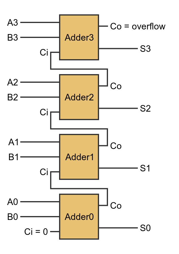
Adder0 adds bit 0 of a to bit 0 of b, to generate bit 0 of the sum s. The carry-in for Adder0 is 0. The carry-out is sent to Adder1.
Adder1 adds bit 1 of a to bit 1 of b, to generate bit 1 of s. The carry-in for Adder1 comes from Adder0. The carry-out is sent to Adder2.
Adder2 and Adder3 work in a similar way. The carry-out from Adder3 is not required. It can be used to indicate a potential overflow condition, but that is not always an error, as described in the binary addition article.
An adder in gates - the half adder
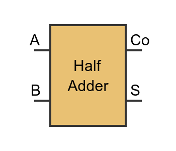
Each adder in the circuit above is identical. Before we look at the logic gates for an adder, we will look at an even simpler case, the half adder.
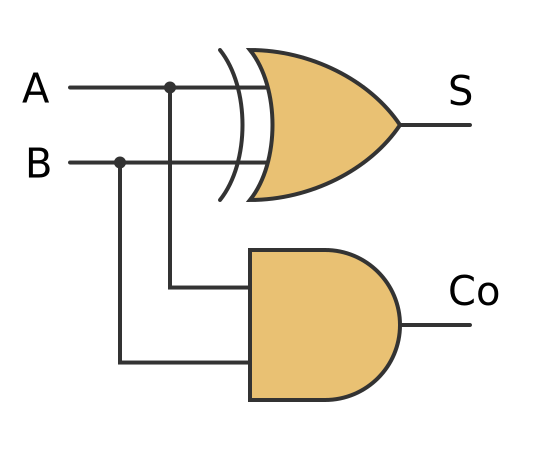
A half adder has 2 inputs, A and B. It doesn't support a carry-in. It has 2 outputs, the sum S and a carry-out. Here is its block representation:
Here is the truth table for the half adder:
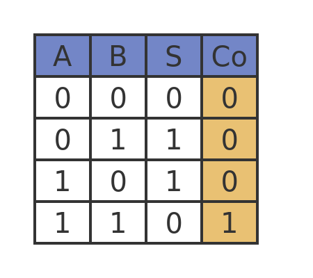
This truth table is equivalent to the first 4 entries of the full binary adder truth table from earlier. The first 4 entries have Ci set to 0. We can see that S is the XOR of A and B, while Co is the AND of A and B. Here is the internal logic of a half adder, showing the XOR gate and the AND GATE:
A full adder
How do we use a half adder to make the full adder from before? Well, as might expect, we use 2 half adders to make a full adder. Well, almost... The actual circuit is shown below:
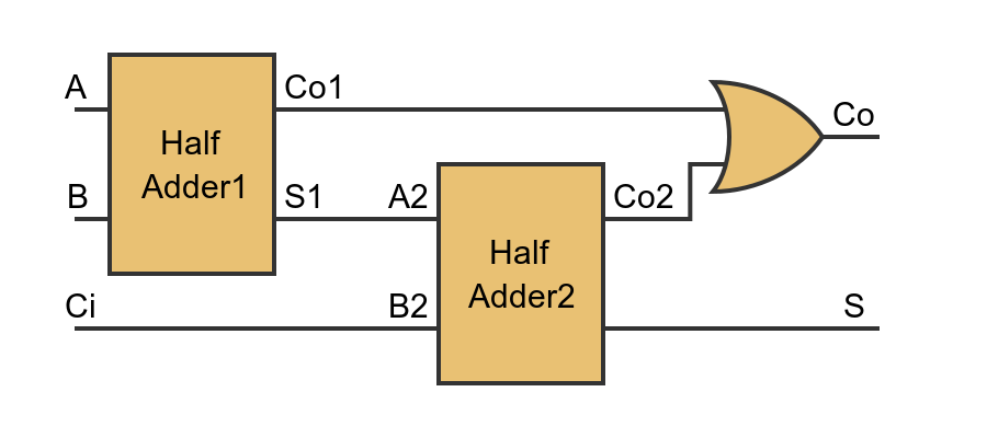
Here we see that Half Adder1 adds the two input bits A and B to create S1. Then Half Adder2 adds the result to the carry-in value Ci. This means that the S output of the second half adder is equal to the 3 inputs (A, B and Ci) added together, which is exactly what we want.
Generating the carry-out requires an extra gate. The final carry bit Co is set if either of the intermediate carry bits (Co1 and Co2) is set. We will show below that this is the correct behaviour.
Full adder carry bit
The full adder requires the carry bit Co to be 1 if at least 2 of the inputs (A, B and Ci) are 1. This is clear from the full adder truth table above. Let's prove that the half adder logic gates give this result. This will also be an opportunity to practise a bit of Boolean algebra.
Co is the result of ORing Co1 and Co2:
Co = Co1 OR Co2
From the half adder logic diagram, we know that:
Co1 = A AND B
We also know that:
Ci OR NOT Ci = 1
This is true because either Ci is true or NOT Ci is true, so ORing them is always true. And since ANDing the original expression with 1 doesn't change its value we have:
Co1 = (A AND B) AND (Ci OR NOT Ci)
Which expands to:
Co1 = (A AND B AND Ci) OR (A AND B AND NOT Ci)
Now let's find the other term, Co2. This is the carry-out term of Half Adder2, which is:
Co2 = S1 AND Ci
S1 is the sum term of Half Adder1, from the half adder logic diagram we know that:
S1 = A XOR B
The XOR term is true if one term is true but the other term is not, so it can be written as:
S1 = (A AND NOT B) OR (NOT A AND B)
Plugging this back into the equation for Co2 gives:
Co2 = ((A AND NOT B) OR (NOT A AND B)) AND Ci
This expands to:
Co2 = (A AND NOT B AND Ci) OR (NOT A AND B AND Ci)
Now we have expression for Co1 and Co2, we just need to OR them together to get Co:
Co = (A AND B AND Ci) OR
     (A AND B AND NOT Ci) OR
     (A AND NOT B AND Ci) OR
     (NOT A AND B AND Ci)
This says that Co will be true if all three of A, B, and Ci are true, or if any 2 of them are true and the other is false. Which is exactly what we need.
Practical considerations - carry ripple
So far we have been considering ideal gates. Real physical gates don't perform exactly like ideal gates.
In particular, when we change the inputs of a gate, the outputs don't change instantly. There is a short delay before the output changes. This delay is very short, typically a few nanoseconds for discrete logic, down to a small fraction of a nanosecond for the gates in a CPU. But this delay is one of the limiting factors in how fast we can clock the CPU, so it is an important factor.
This delay presents a particular problem for an adder. Here is the diagram of the adder again:
Let's imagine we present the values A0 to A3 and B0 to B3, all at the same instant. And let's say that an adder takes a time dt before its outputs reflect the state of its inputs.
The output of Adder0 only depends on A0 and B0, so its outputs (the sum and carry out) will be valid after the time dt.
But what about Adder1? This depends on A1, and B1, but also the carry-out value from Adder0. Now the Adder0 carry-out value isn't valid until time dt. This means that the inputs to Adder1 aren't all valid until time dt. Then there is then a delay of another dt until the outputs of Adder2 are valid. So those outputs will not be valid until time 2 dt.
Adder2 depends on the carry-out from Adder1, which isn't valid until time 2 dt. It takes another dt for the outputs of Adder2 to reflect the input values, so Adder2 will not be ready until time 3 dt.
In a real CPU, the adder circuit might be 64 bits wide, so the adder result wouldn't be available until time 64 dt. Even with very fast gates that is a long time (when you consider that a modern CPU has several clock cycles per nanosecond).
This type of adder is called a ripple carry adder because the carry bit has to ripple through the adder before the result is valid.
We won't go into detail here, but there are strategies to reduce this delay. For example, the adder could include logic that looks at inputs A0, B0, A1 and B1 all together to calculate S0 and S1 plus the carry-out all in one operation. This would mean that bits 0 and 1 would be valid at time dt, bits 2 and 3 would be valid at time 2 dt, and so on. This alone would double the speed of the adder. In practice, more sophisticated methods are used to reduce the delay even further.
Related articles
Join the GraphicMaths Newsletter
Sign up using this form to receive an email when new content is added to the graphpicmaths or pythoninformer websites:
Popular tags
adder adjacency matrix alu and gate angle answers area argand diagram binary maths cardioid cartesian equation chain rule chord circle cofactor combinations complex modulus complex numbers complex polygon complex power complex root cosh cosine cosine rule countable cpu cube decagon demorgans law derivative determinant diagonal differential equation directrix dodecagon e eigenvalue eigenvector einstein ellipse equilateral triangle erf function euclid euler eulers formula eulers identity exercises exponent exponential exterior angle first principles flip-flop focus gabriels horn galileo gamma function gaussian distribution gradient graph hendecagon heptagon heron hexagon hilbert horizontal hyperbola hyperbolic function hyperbolic functions infinity integration integration by parts integration by substitution interior angle inverse function inverse hyperbolic function inverse matrix irrational irrational number irregular polygon isomorphic graph isosceles trapezium isosceles triangle kite koch curve l system lhopitals rule limit line integral locus logarithm maclaurin series major axis matrix matrix algebra mean minor axis n choose r nand gate net newton raphson method nonagon nor gate normal normal distribution not gate octagon or gate parabola parallelogram parametric equation pentagon perimeter permutation matrix permutations pi pi function polar coordinates polynomial power probability probability distribution product rule proof pythagoras proof pythagorean triple quadrilateral questions quotient rule radians radius rectangle regular polygon rhombus root sech segment set set-reset flip-flop simpsons rule sine sine rule sinh slope sloping lines solving equations solving triangles special relativity speed of light square square root squeeze theorem standard curves standard deviation star polygon statistics straight line graphs surface of revolution symmetry tangent tanh transformation transformations translation trapezium triangle turtle graphics uncountable variance vertical volume volume of revolution xnor gate xor gate