Simple flip-flops
Categories: logic computer science
A flip-flop is a particular arrangement of logic gates that uses positive feedback to store persistent information about previous states of its inputs.
Most simple arrangements of logic gates can be described by a truth table that defines all its output values as a logical function of its current input values. Its outputs only depend on the value of its inputs at that exact moment, and the system of gates has no "memory" of what the states of its inputs were at any time in the past.
A flop-flop behaves differently. The current state of its outputs doesn't only depend on the current inputs. They might also depend on past states of the inputs.
Latches vs flip-flops
Technically the circuits described here are latches rather than flip-flops. However, the term flip-flop is often used as a generic term covering both types, and that is how we are using it here. The difference between a latch and a flip-flop is described in the article on d-type-flip-flops.
Logical feedback
This first circuit is the simplest possible example of a flip-flop. It isn't particularly useful, but it illustrates the principle of positive feedback. Here is the circuit:
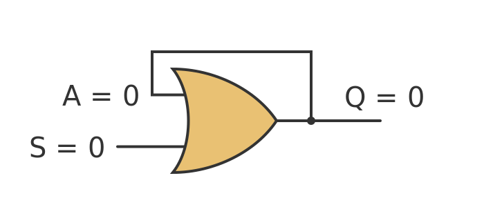
In this circuit, the output of the gate, Q is connected to one of the inputs, A, of the gate. Although they are labelled separately as Q and A, they are connected together, so they must always have the same value.
We start with input S set to 0. Let's assume that when we first power the circuit up, the output Q also settles at 0 (this is a big assumption, but the circuit described here is not something you would ever use in real life, so let's make that assumption for the sake of simplicity).
So S is 0 and Q is 0, which means that A must also be 0. And since 0 ORed with 0 is 0, everything is perfectly consistent.
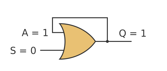
Now let's set S to 1:

The gate is an OR gate, so the output will be 1 if either input is 1. When we set S to 1, the output Q will change to 1. This in turn forces A to go to 1. Now we have an OR gate with both inputs set to 1 and its output still 1, which is perfectly consistent. The state is consistent at every point - S is 1, so Q is 1, so A is 1, which is still consistent with Q being 1.
This is where things get interesting. We will now set S back to 0:
When we set S to 0, Q doesn't change. That is because now A is set to 1, so the output of the gate doesn't change when S changes. Once again the system is consistent.
Notice, though, that input S is now set back to 0 just as it was at the start. But this time Q is 1 rather than 0. This is because there are 2 stable states when S is 0:
- One stable state is where Q is 0 therefore A is 0 - so both inputs are 0 and the output is 0.
- The other stable state is where Q is 1 therefore A is 1 - so one of the inputs is 1 and the output is 1.
These states are both self-consistent and setting S to 1 then back to 0 flips the system from the first state to the second.
The system can, in effect, remember whether S has ever been set to 1 at any point in the past.
Unfortunately, once the circuit has flipped, there is no way to reset it. We will address that problem next.
Set-reset flip-flop
A set-reset (or SR) flip-flop is slightly more useful and forms the basis for several other types of common flip-flops. It has 2 inputs, S (set) which sets the output to 1, and R (reset) which sets the output to 0.
It also has 2 outputs. Q is the main output that is set or reset by S and R. It also has an output that is the inverse of Q. The second output is a necessary part of the way the flip-flop works, and it is usually made available in case it is useful to the external logic that uses the flip-flop.
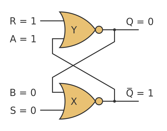
Here is a diagram of a set-reset flip-flop using NOR gates:
In this arrangement, there are now 2 feedback paths. The output of gate X feeds into the input of gate Y, and vice versa.
As before we have labelled the feedback inputs. The input to gate X is labelled B but since it is connected to output Q, then B will always equal Q. Similarly, the input to gate Y, labelled A, will always equal .
This time the gates are inverting gates, but the feedback path goes through both gates. For example S goes through gate X, then through gate Y, before being fed back into gate X. This means that the system still uses positive feedback (because the two inversions cancel out).
Let's look at that in more detail. We will start with both inputs held at 0. The first thing to realise is that there is no stable state where both outputs are 0. Imagine if this were the case:
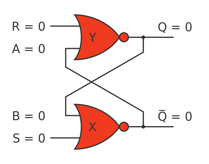
If both outputs were 0, then R and A would both be 0 and S and B would both be 0. But if R and A were both 0 then Q would be 1. And if S and B were both 0 then would be 1. Which would mean A and B would both be 1, so Q and would be 0, and so on. There is no consistent state where both outputs are 0, and also no consistent state where both outputs are 1.
If this were an episode of Star Trek, of course, the computer would scream "illogical" and burst into flames. In reality one of the gates will end up with an output of 1, and the other will end up with an output of 0, and the system will be stable. It is impossible to say which output will end up at 1 because the circuit is symmetrical. But in a real-life circuit, one of the gates will have a slightly faster transistor, or else a tiny bit of electrical noise will push one gate over the edge, and stability will be achieved pretty much instantaneously.
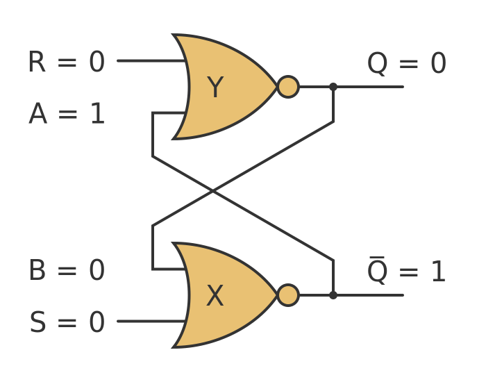
Let's assume it settles with Q at 0. It doesn't matter if they happened to be the other way around, we will look at both cases. This is the circuit with S, R and Q at 0:
This is completely consistent. B and S are 0, so the output of X (ie ) is 1. This means that R is 0 and A is 1 so the output of Y (ie Q) is 0. This is consistent with B being 0, so everything is consistent.
Setting Q
Now let's set S to 1:
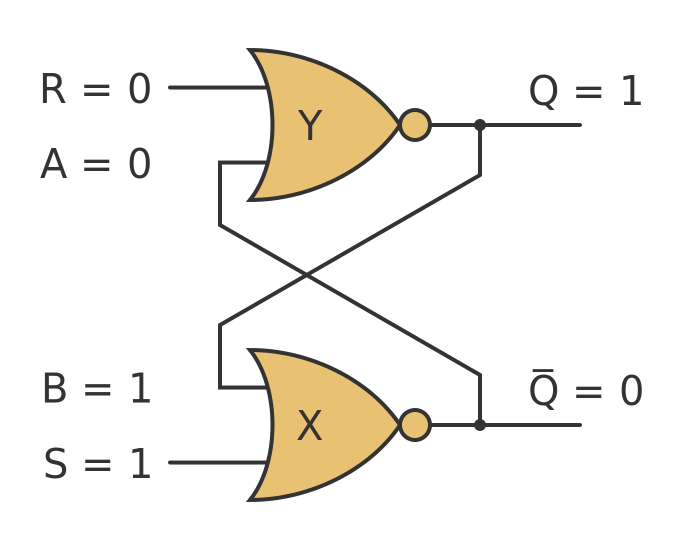
Setting S to 1 on gate X causes to go to 0. This means that A on gate Y goes to zero, so Q goes to 1. This means that B is also 1.
In effect, setting S to 1 results in Q being set to 1. This is now a consistent, stable value.
Now see what happens when we set S back to 0:
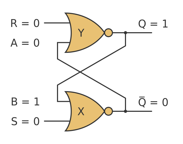
Since B is already set to 1, changing S makes no difference. Setting S to 0 doesn't affect the state at all. So we now have the same inputs as we had right at the start, but this time Q is 1 rather than 0. When both inputs are 0, then both possibilities are consistent and stable.
Resetting
Assuming we are in a state where both inputs are 0, and Q is 1, we can take the R input to 1 to reset the flip-flop back to the state where Q is 0 again:
The logic here is exactly the same as before. Rather than describing it again, it is worth noting that the circuit is symmetrical. If we swap inputs S and R, and swap outputs Q and , we have the same situation as we had when we looked at the behaviour of S and Q earlier. So setting the R input to 1 sets to 1.
Invalid inputs
What if we set S and R both to 1 at the same time, we get this situation:

This configuration is stable, but it isn't considered valid because Q and are both 0. We would normally expect them to be inverses of each other (i.e. one should be 0 and the other 1 at all times).
A problem can arise from this state if the 2 inputs are both set to 0 at exactly the same time. Since the system is entirely symmetrical, there is nothing to say whether Q or should be set, so the state after that event would be indeterminate. That would be similar to the situation when the system is first powered up. However, having an indeterminate state while the system is running is a lot worse than having an indeterminate state when the system starts up.
For this reason, simple set-reset flip-flops are rarely used in real systems. Extra logic is usually added to avoid these problems.
Using NAND gates
It is possible to create a similar flip-flop using NAND gates, like this:
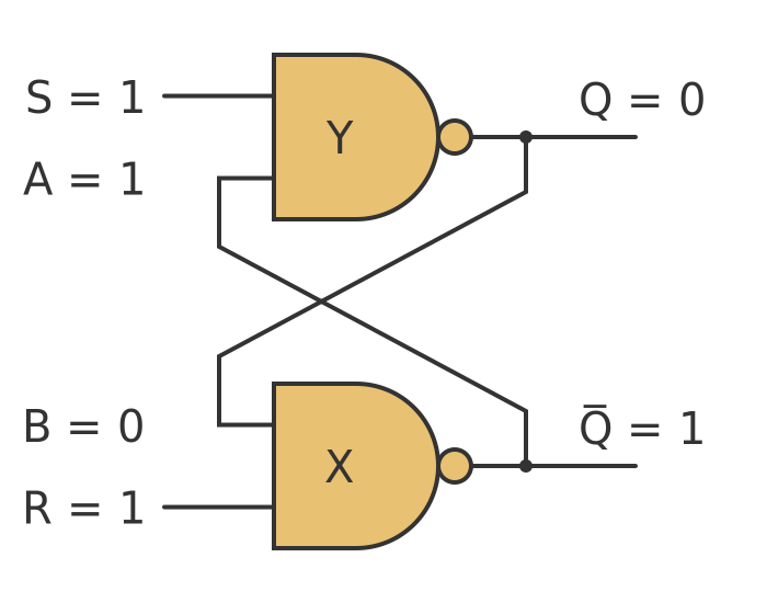
This works in a similar way, except that the S and R inputs are swapped. The sense of these two inputs is also inverted - the 2 inputs should normally be both set to 1 rather than 0. The flip-flop can be set by taking S to 0 and then back to 1. It can be reset by taking R to 0 and then back to 1. The inputs should not both be set to 0 at the same time.
Related articles
Join the GraphicMaths Newsletter
Sign up using this form to receive an email when new content is added to the graphpicmaths or pythoninformer websites:
Popular tags
adder adjacency matrix alu and gate angle answers area argand diagram binary maths cardioid cartesian equation chain rule chord circle cofactor combinations complex modulus complex numbers complex polygon complex power complex root cosh cosine cosine rule countable cpu cube decagon demorgans law derivative determinant diagonal differential equation directrix dodecagon e eigenvalue eigenvector einstein ellipse equilateral triangle erf function euclid euler eulers formula eulers identity exercises exponent exponential exterior angle first principles flip-flop focus gabriels horn galileo gamma function gaussian distribution gradient graph hendecagon heptagon heron hexagon hilbert horizontal hyperbola hyperbolic function hyperbolic functions infinity integration integration by parts integration by substitution interior angle inverse function inverse hyperbolic function inverse matrix irrational irrational number irregular polygon isomorphic graph isosceles trapezium isosceles triangle kite koch curve l system lhopitals rule limit line integral locus logarithm maclaurin series major axis matrix matrix algebra mean minor axis n choose r nand gate net newton raphson method nonagon nor gate normal normal distribution not gate octagon or gate parabola parallelogram parametric equation pentagon perimeter permutation matrix permutations pi pi function polar coordinates polynomial power probability probability distribution product rule proof pythagoras proof quadrilateral questions quotient rule radians radius rectangle regular polygon rhombus root sech segment set set-reset flip-flop simpsons rule sine sine rule sinh slope sloping lines solving equations solving triangles special relativity speed of light square square root squeeze theorem standard curves standard deviation star polygon statistics straight line graphs surface of revolution symmetry tangent tanh transformation transformations translation trapezium triangle turtle graphics uncountable variance vertical volume volume of revolution xnor gate xor gate