Combining logic gates
Categories: logic computer science
We have previously seen how the individual logic gates operate. This article looked at AND, OR, and XOR gates, and their inverting versions.
Individual logic gates can't do very much on their own, it is when we combine them that the functionality gets interesting. As a first step, we will look at some examples of combining a few gates, and how to analyse them to derive a truth table that shows the combined behaviour.
Combining two logic gates
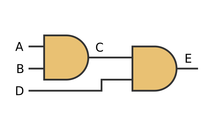
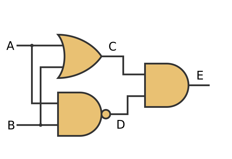
Here is a very simple combination of an AND gate plus an OR gate:
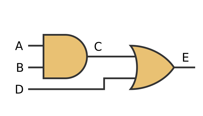
The combination has three inputs (A, B and D), and one output (E). We have also labelled an intermediate point C as this will be useful for deriving the truth table.
Creating the truth table
For combinations of gates, we create the truth table step by step, starting at the inputs, calculating the intermediate points, and finally calculating the output.
In this case, inputs A and B are combined by the AND gate to give output C. Input D is combined with C by the OR gate, to give the final result E. The value E is dependent on all 3 inputs A, B and D.
Here is the truth table that generates C from A and B:
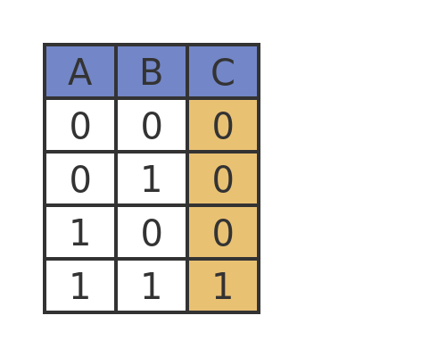
This is just the standard truth table for an AND gate.
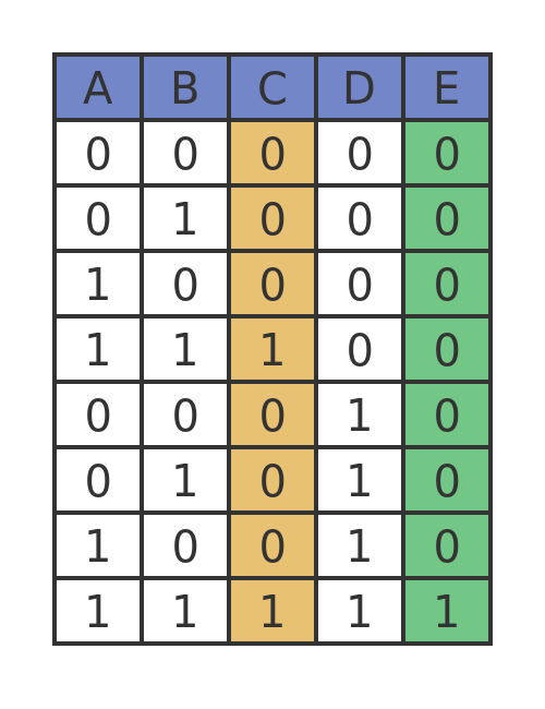
We now need to combine C with the third input signal D. Since there are 3 inputs, there are 8 combinations of input values (2 times 2 times 2). So we need an 8-line truth table:

The top 4 lines contain the 4 combinations of A and B, with D set to 0. The bottom 4 lines repeat the same 4 combinations of A and B, but with D set to 1. This means that all 8 possible combinations are included.
The output E if 1 is either C or D (or both) are 1, otherwise it is 0.
3-input AND gate
The most commonly used gates have 2 inputs, but sometimes it is useful to have a gate with more than 2 inputs. For example, we might want an AND gate that has 3 inputs.
What would we expect a 3-input AND gate to do? For a 2 input AND gate, the output is 1 if both inputs are 1, and 0 otherwise. So for a 3-input AND gate, we would expect the output to be 1 if all 3 inputs are 1, and 0 otherwise.
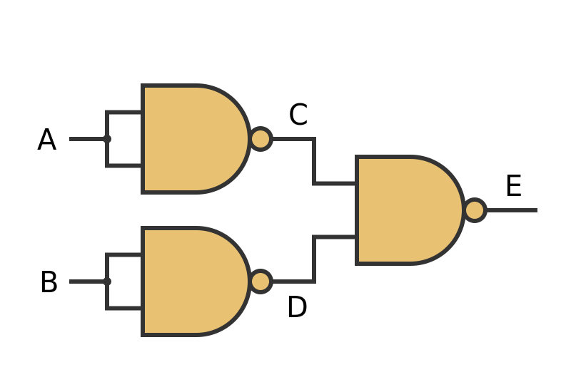
While it is possible to design gates with more than 2 inputs, it is often more convenient to use a combination of 2-input gates to rather than making a special 3-input gate. In this example, we will create a 3-input AND gate from a couple of 2-input AND gates.
Here is the circuit diagram for this:
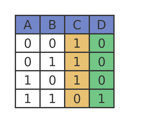
This is a similar layout to the previous example, except that both gates are AND gates. Here is the resulting truth table:
In this case, the intermediate value C is 1 only if A and B are both 1. Output E is 1 only if C and D are both 1. This means that all 3 inputs must be 1 for the output to be 1, otherwise the output will be 0.
We won't go through it here, but it is fairly easy to show that connecting 2 OR gates in the same configuration creates a 3-input OR gate. In that case, the output is 0 if all the inputs are 0, otherwise it is 1.
3-input XOR gate
What about a 3-input XOR gate? One problem here is to decide what exactly it should do.
We know the behaviour of a 2-input XOR gate. It is 0 if both inputs are 0, 1 if either input is 1, and 0 if both inputs are 1. But when we apply this to the 3-input case, it could have 2 possible interpretations:
- The output is 0 if all the inputs have the same value, and 1 otherwise.
- Or, the output is 0 if an even number of inputs is set to 1, and 1 otherwise.
The second interpretation is usually the most useful. So if all the inputs are 0, or if exactly 2 inputs are set to 1, the output will be 0. If exactly 1 input is set to 1, or if all 3 inputs are set to 1, the output will be 1.
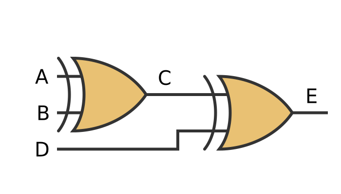
It also turns out that, if we take that interpretation, then joining 2 XOR gates in the same configuration as the AND case above does exactly what we need:
Here is the truth table for the 3-input XOR gate:
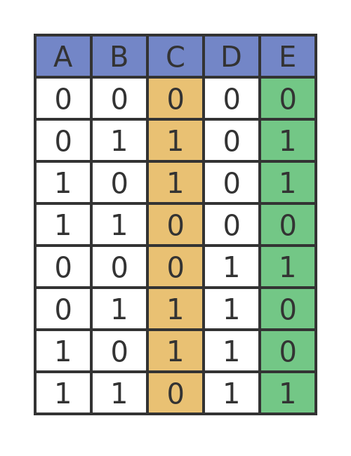
We can see from the truth table that C is A XORed with B, and E is C XORed with D. If you check the value of E for every value of A, B and D, you will see that it is indeed 0 if an even number of inputs is set to 1, and 1 if an even number of
Creating an XOR gate
While we are on the subject of XOR gates, let's look at how we might create one from other gates. The process we use can be used wherever you need to implement some simple logic using basic gates.
We start by describing the conditions under which we would want a result of 1. For an XOR gate with inputs A and B we expect a result of 1 if either A or B, but not both, is 1. By implication, under any other circumstances, we expect a 0.
Look at the truth table in the logic gates article if you are not convinced the statement above is true.
We now want to express the same condition using only AND, OR, and NOT operators, because they are our basic gates.
"Either A or B" can be written as A OR B. "not both" can be written as NOT (A AND B). Since we need both of these to be true for the XOR condition to be true, we can express the logic of an XOR gate as:
(A OR B) AND (NOT (A AND B))
This can be implemented in gates like this:
Output C represents (A OR B), output D represents (NOT (A AND B)), and of course E is the result of ANDing those values together. Here is the truth table:

Universal gates
It is possible to use a combination of gates to simulate a different type of gate. This is sometimes useful in designing digital circuits, as we will see below.
It is actually possible to create any type of gate from one or more NAND gates. The NAND gate is sometimes called the universal gate for that reason.
As an aside, you can just as easily create any type of gate from one or more NOR gates, so NOR gates are also universal gates. Notice that AND gates and OR gates aren't universal because it is impossible to create a NOT gate with either of those gates. XOR/XNOR gates can also be used as universal gates, because V XOR 1 gives NOT V, but in practice using these gates is more often complicated than it is worth.
We will look at some examples here, using NAND gates.
First, we can use a NAND gate to create a NOT gate, like this:
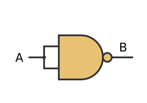
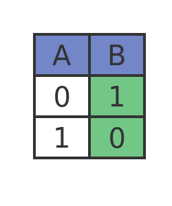
What we have done here is simply connect the 2 inputs together. So when A is 0, both inputs to the NAND gate are 0, so the output is 1. When A is 1, both inputs to the NAND gate are 1, so the output is 0. The truth table is the same as a NOT gate:
Armed with this NOT gate, we can now use 2 NAND gates to create an AND gate:
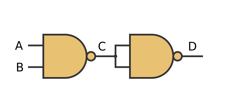
What we have done here is attach a NOT gate to the output of a NAND gate.
Now we know that a NAND gate is just like an AND gate followed by a NOT gate. By adding an extra NOT gate, we effectively have an AND gate followed by 2 NOT gates. The 2 NOT gates cancel out, leaving us with just an AND gate. Here is the truth table:
Finally, we can create an OR gate from NAND gates!
We do this using De Morgan's Law. This law states that:
(NOT A) AND (NOT B) = NOT (A OR B)
This law is a rule of inference. As an example, suppose that a shop is closed on Thursdays and Sundays. There are two ways to express when the shop is open.
We can say that the shop is open if the day is not Thursday and the day is not Sunday.
Or we can say that the shop is open if it is not true that the day is Thursday or that the day is Sunday.
We can apply an extra NOT to each side, giving us:
NOT ((NOT A) AND (NOT B)) = A OR B
The double NOT on the right-hand side cancels out. Substituting a NAND for the NOT AND gives us:
(NOT A) NAND (NOT B) = A OR B
Here is the left-hand side implemented in logic gates:
And here is the truth table

Column C is NOT A, and column D is NOT B. When we NAND them together we get the OR function.
But why would we ever want to do this?
Well, simple digital circuits are sometimes created using discrete logic chips. These are integrated circuits that contain a small number of individual logic gates (as opposed to CPUs and other complex chips that contain many millions of gates).
These chips are standard components that usually contain several gates of the same type. For example, there are chips available that contain 4 OR gates, and other chips that contain 4 NAND gates, and so on.
Now imagine that we were designing a circuit that required a single OR gate, and a single NAND gate. We could use 2 chips, one with 4 OR gates and the other with 4 NAND gates. But we would only be using 1 gate out of each chip.
Or we could just use a NAND chip. We would use 3 of the NAND gates to create an OR gate, and the remaining NAND gate as a NAND gate. We have saved an entire chip, making the product smaller and cheaper.
Related articles
Join the GraphicMaths Newsletter
Sign up using this form to receive an email when new content is added to the graphpicmaths or pythoninformer websites:
Popular tags
adder adjacency matrix alu and gate angle answers area argand diagram binary maths cantor cardioid cartesian equation chain rule chord circle cofactor combinations complex modulus complex numbers complex polygon complex power complex root cosh cosine cosine rule countable cpu cube decagon demorgans law derivative determinant diagonal differential equation directrix dodecagon e eigenvalue eigenvector einstein ellipse equilateral triangle erf function euclid euler eulers formula eulers identity exercises exponent exponential exterior angle first principles flip-flop focus gabriels horn galileo gamma function gaussian distribution gradient graph hendecagon heptagon heron hexagon hilbert horizontal hyperbola hyperbolic function hyperbolic functions infinity integration integration by parts integration by substitution interior angle inverse function inverse hyperbolic function inverse matrix irrational irrational number irregular polygon isomorphic graph isosceles trapezium isosceles triangle kite koch curve l system lhopitals rule limit line integral locus logarithm maclaurin series major axis matrix matrix algebra mean minor axis n choose r nand gate net newton raphson method nonagon nor gate normal normal distribution not gate octagon or gate parabola parallelogram parametric equation pentagon perimeter permutation matrix permutations pi pi function polar coordinates polynomial power probability probability distribution product rule proof pythagoras proof pythagorean triple quadrilateral questions quotient rule radians radius rectangle regular polygon rhombus root sech segment set set-reset flip-flop simpsons rule sine sine rule sinh slope sloping lines solving equations solving triangles special relativity speed of light square square root squeeze theorem standard curves standard deviation star polygon statistics straight line graphs surface of revolution symmetry tangent tanh transformation transformations translation trapezium triangle turtle graphics uncountable variance veridical paradox vertical volume volume of revolution xnor gate xor gate